What Are the Top 10 Engine Control System Parts?
Modern engines depend on coordinated electronic decisions, not isolated mechanical parts. Engine Control System Parts measure conditions, process data, and adjust fuel, air, ignition, and emissions. A small sensor fault can create rough idling, slow acceleration, or difficult starting.
This guide examines ten essential components found in many gasoline and diesel control systems. The list includes the engine control unit, crankshaft and camshaft sensors, oxygen sensors, fuel injectors, ignition coils, throttle control components, and supporting wiring. Relays, fuses, and pressure sensors also deserve attention because a simple power interruption can imitate a major computer failure.
Practical diagnosis requires more than replacing the most obvious part. Technicians compare scan-tool data with service specifications, inspect connectors, and test voltage under load. They also consider engine temperature, maintenance history, and fault-code patterns. That matters.
No list is perfect. Vehicle design changes by manufacturer, model year, fuel type, and emissions standard. Some systems combine several functions inside one assembly. Others use separate modules that communicate through a vehicle network. This article therefore explains each part’s role, common symptoms, and basic inspection considerations without treating every fault as universal. Reliable conclusions should come from verified specifications and tested evidence, not guesswork. Even experienced technicians can miss a damaged ground connection. A careful method remains essential.
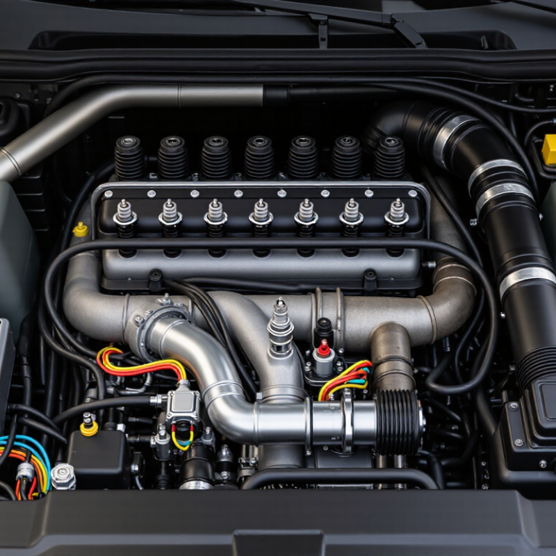
Engine Control Systems: Purpose, Structure, and Core Functions
What Are the Top 10 Engine Control System Parts?
Engine control systems manage fuel, air, ignition, emissions, and engine protection. Their structure usually has three layers: sensors collect data, the control unit processes it, and actuators adjust engine operation. In practical diagnosis, the electronic control unit is the central decision-maker. It compares sensor signals with stored operating maps, then changes outputs within milliseconds.
The ten key parts include the electronic control unit, crankshaft position sensor, camshaft position sensor, mass airflow sensor, throttle position sensor, engine coolant temperature sensor, oxygen sensor, fuel injectors, ignition coils, and electronic throttle actuator. The crankshaft and camshaft sensors establish timing. The airflow and throttle sensors measure engine demand. The coolant sensor reflects temperature during cold starts. Oxygen feedback helps correct the fuel mixture. Injectors deliver measured fuel, while ignition coils create the spark. The throttle actuator controls incoming air.
Small details matter. A loose connector can imitate a failed sensor. Moisture near a wiring plug may create unstable readings. During inspection, technicians should compare live data with actual conditions, such as coolant temperature after an overnight stop. A scan code is evidence, not a final diagnosis. Sometimes the control unit is blamed too quickly. The system’s design is precise, but not flawless. Calibration differences, wiring resistance, and mechanical wear can distort otherwise believable signals.
The Top 10 Engine Control System Parts and Their Roles
What Are the Top 10 Engine Control System Parts?
The engine control unit, or ECU, processes sensor data and adjusts fuel, ignition, and emissions functions. It is the system’s decision center. The crankshaft position sensor tracks engine speed and piston timing. The camshaft position sensor identifies valve timing and helps control injection sequences. The throttle position sensor reports pedal and throttle movement to the ECU. A small signal matters.
The mass airflow sensor measures incoming air, supporting accurate fuel calculation. The manifold absolute pressure sensor reads intake pressure and helps estimate engine load. The coolant temperature sensor tells the ECU whether the engine is cold, warm, or overheating. The oxygen sensor checks exhaust oxygen levels and supports closed-loop fuel correction. Its readings can drift with age, so replacement alone may not solve a fault.
The fuel injector delivers measured fuel into the intake path or combustion chamber. A clogged injector can create rough running, uneven acceleration, or hard starting. The ignition coil raises battery voltage high enough to produce a spark at the plug. Weak coils often reveal themselves under load, not during idle tests. In workshop diagnostics, technicians should inspect wiring, grounds, connectors, and live data before changing parts. That step is sometimes skipped. A stored fault code identifies a circuit or reading, but it does not always prove a failed component. Proper testing still requires service specifications, safe procedures, and careful comparison with real engine behavior.
Common Faults, Testing Methods, and Part Replacement Considerations
What Are the Top 10 Engine Control System Parts?
Common Faults, Testing Methods, and Part Replacement Considerations
The ten parts most often examined are the engine control unit, crankshaft sensor, camshaft sensor, mass airflow sensor, throttle-position sensor, coolant-temperature sensor, oxygen sensor, fuel injector, ignition coil, and manifold-pressure sensor. These components control fuel, ignition, airflow, and emissions. The U.S. Environmental Protection Agency’s 2023 Automotive Trends Report recorded average new-vehicle efficiency at about 27 miles per gallon, showing how closely control accuracy affects performance.
Fault symptoms can overlap. A rough idle may involve a vacuum leak, weak ignition coil, dirty injector, or incorrect sensor data. Technicians should scan stored and pending codes, then compare live data with service specifications. A multimeter checks voltage and resistance. An oscilloscope can reveal a distorted crankshaft signal. Fuel-pressure testing helps separate injector faults from pump or regulator problems. Do not replace parts by code alone.
Replacement decisions require evidence. Inspect connectors, wiring, grounds, and contamination before ordering components. A coolant sensor coated with residue may only need cleaning, but damaged wiring needs repair. New control units may require programming and calibration. After replacement, clear codes, perform a road test, and confirm emissions monitors have completed. The International Organization of Motor Vehicle Manufacturers reported more than 93 million vehicles produced globally in 2023, so repair quality matters at enormous scale. Still, diagnostic data can mislead. I have seen “bad sensors” blamed for mechanical faults. Testing first is slower, but often cheaper.